After not being able to properly cut the linear rods to proper lengths and make ridges in them due to a lack of a metalworking lathe, we decided to turn to Aliexpress for yet another thing that we originally planned to do differently.
We reached out to multiple suppliers of linear rods and asked if they could cut the rods to our pre-defined lengths as well as create adequate ridges for the e-clips that we have already bought. Most of the suppliers were happy to cut the rods to custom lengths, but only one also had the ability to create the ridges. In the end, we paid the same amount for the materials, but also had to pay around $40 for the work, which seemed an adequate amount considering that we got the parts exactly as ordered.
While waiting for these, as well as some replacement parts needed for the hardware assembly of the rover body, we realized we had pretty much all the parts required to put together the electronics of the rover.
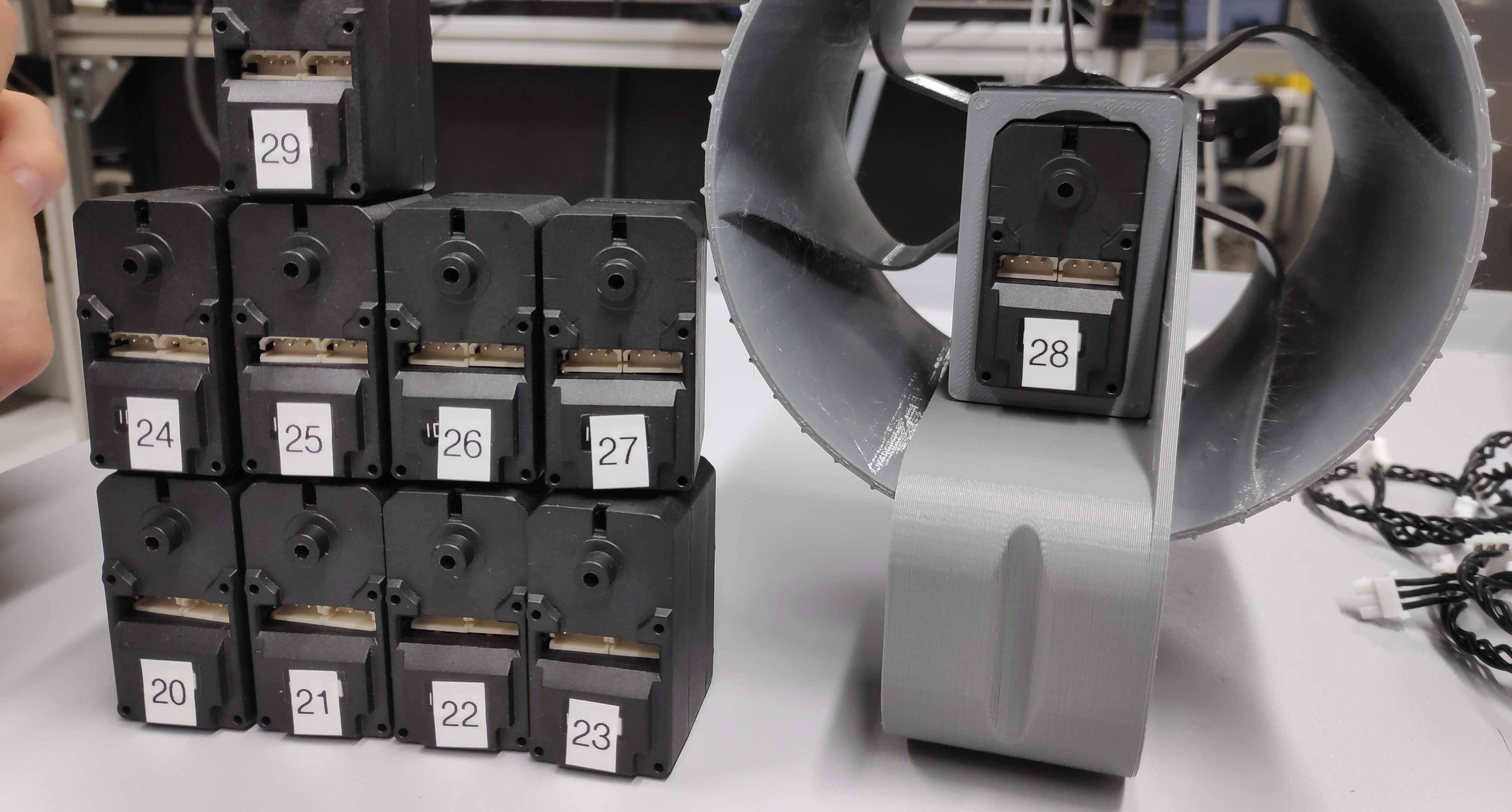
Assigning unique IDs to motors
We started by testing each and every one of the 10 motors and using the utility describe in the previous post to assign each motor a unique ID, in order to control them all from one controller. We used the IDs from the original project for now, in order to have a compatible configuration with the original project.
Soldering (almost) everything
After that, we left the motors as they were and focused on the electronics from the other side of the circuit, starting with the battery. The two batteries we ordered had incompatible connectors, so we had to cut the endings off and replace them with different connectors from the junction adapter that we also ordered.
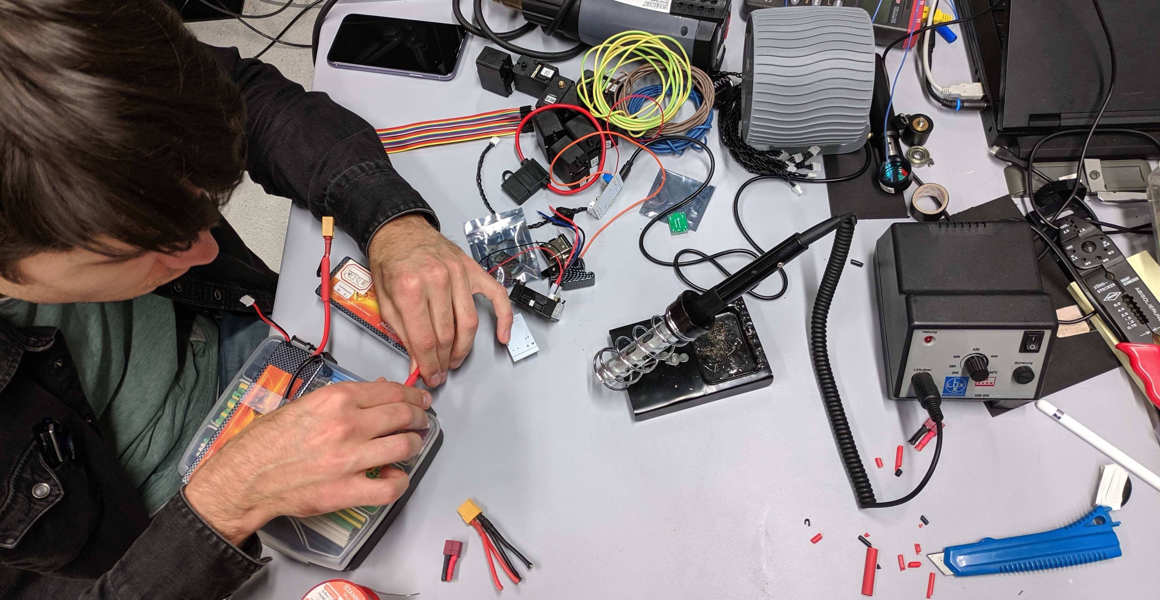
The next thing on the list was completing the circuit up to the voltage converter for the Raspberry Pi, as well as the motor control board. This meant soldering the power switch, volt meter, fuse holder and 5V regulator at the correct distances and adding a few pins for the Raspberry Pi. We ended up with a slightly different circuit than the one published by Roger, but The main difference is how the 5V regulator is wired in our setup.
We have also prepared the Raspberry Pi and flashed it with the current (Raspbian buster) operating system. We went through the instructions to install the SVGHK packages and prepared the Raspberry Pi to drive all of the motors.
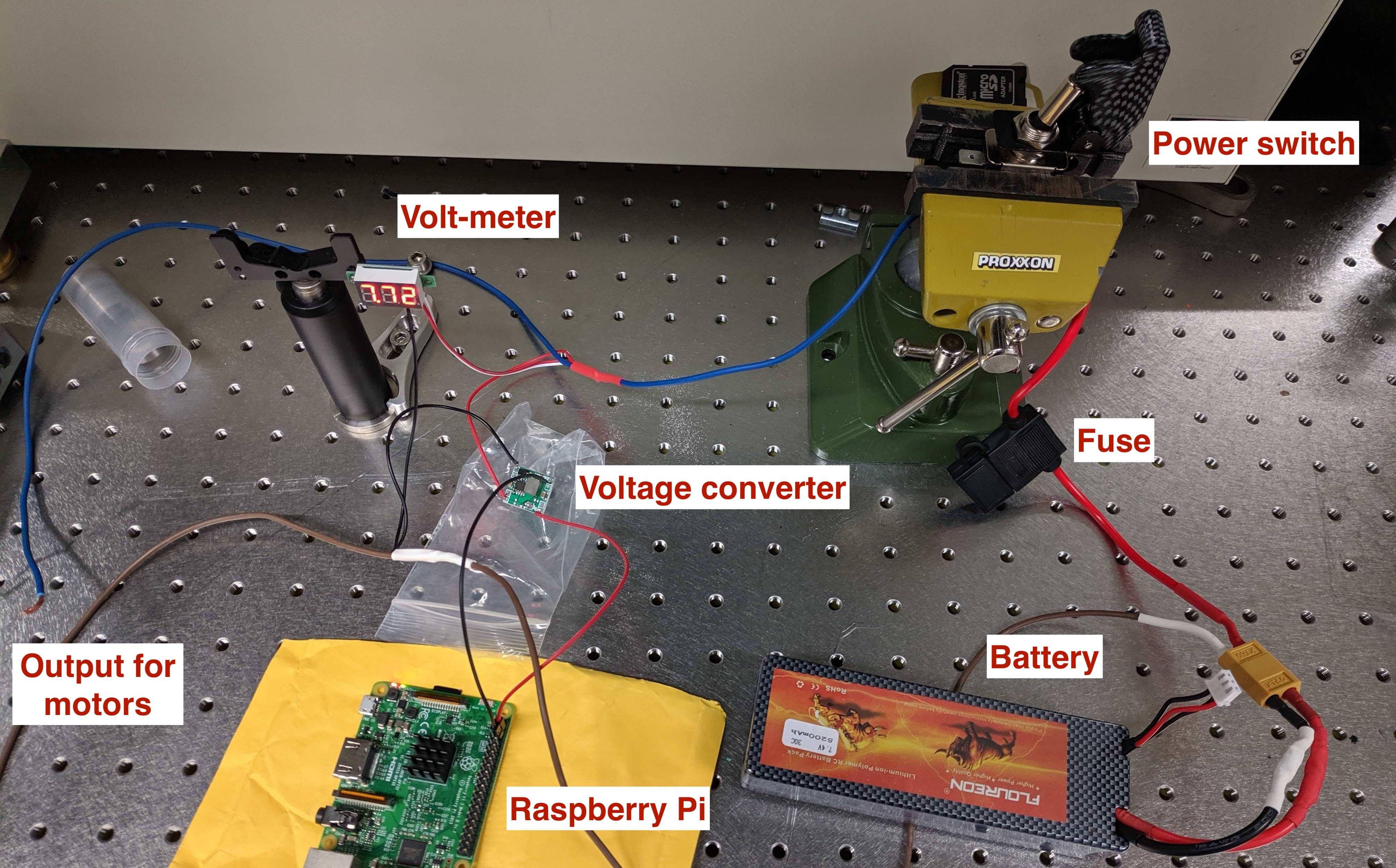
Ready to roll
After this update, we have all the electronics ready to go, and the next step is to finish assembling the body and place the main part of the electronics into the proper place on the rover. After that, we will have to place the motors in their correct positions and then properly wire them with cables of appropriate lengths.